← All SimuRC-PRO documentation
Hsimracing
Configuration Guide
SimuRC-PRO · ELRS pairing · RP2040 setup · first run
Each chapter below can be expanded or collapsed by clicking its title. The chapters are designed to be read in order on a first read, but you can come back to any of them anytime.
Disclaimer
This project involves electronic equipment, radio transmission, moving RC vehicles, and user modifications that may present risks if used improperly. All assembly, wiring, configuration, testing and use are performed entirely at the user’s own responsibility. The creators, developers, manufacturers and distributors of this project cannot be held responsible for injuries, accidents, property damage, improper use, incorrect installation, misuse, or any consequences resulting from the use of this system. This project is intended for responsible and informed users only. Minors must be supervised by a responsible adult during installation, configuration, testing and operation. Always test in a safe environment, with the vehicle secured and clear of people, animals and obstacles. Before powering on the buggy, remove the wheels to ensure there is no risk of unintended movement. Keep long hair away from the motor and rotating parts. Never place fingers or objects inside mechanisms that may suddenly move.
Each step depends on the previous one. Follow the procedure carefully, in order. Skipping ahead is the most frequent cause of “it does not work.”
Quick start (TL;DR)
If you already know your way around ELRS and just want the ten-second version, here it is. Each line links to the chapter that explains it in detail.
- Install SimuRC-PRO and activate your licence. Details
- Flash the RP2040 with
uart_bridge.uf2. Skip if you use Direct USB. Details - Wire the RP2040 to the TX (Black / Red / White, or only White if dual USB power). Skip if Direct USB. Details
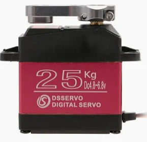
- Wire the RX inside the RC car: CH1 to the steering servo, CH2 to the ESC. Details
- Set the same binding passphrase on the TX and the RX over Wi-Fi (
http://10.0.0.1). Details - Run Axis Calibration in the app (pure software, no TX needed yet). Details
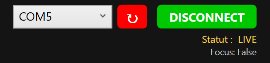
- Plug TX in USB, pick the COM port, power the RC car, then run Buggy Calibration. The wizard opens its own ELRS connection internally to move the servo while you set the mechanical end-stops. The main Connect button is locked until this is done. Details
- Click Connect (now unlocked), map an ARM button, leave the power profile on Beginner 20%, drive carefully on the first run. Safety details · First run details
If anything looks unclear in this list, jump to the relevant chapter below for the full explanation, screenshots and warnings. New to ELRS? Read the Glossary first.
Hardware overview
This guide refers to three components using short names. Take a moment to identify each one before starting. You can likely use hardware from other brands or models that work in a similar way. If you do, please let us know about the compatibility by emailing contact@hsimracing.com so we can keep an up-to-date list. SimuRC-PRO talks to your buggy through the ExpressLRS (ELRS) long-range radio protocol, which is at the core of the whole system.
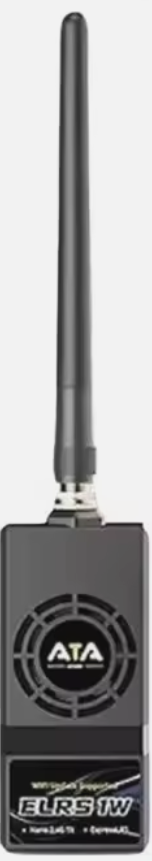
TX — Transmitter
Long-range ELRS transmitter (Radiolink ATA Nano 1W, Radiomaster Ranger Nano, Radiomaster Ranger Micro, etc.). Connects to the RP2040 board (or directly via USB on supported modules) and broadcasts the radio link to the RC car.
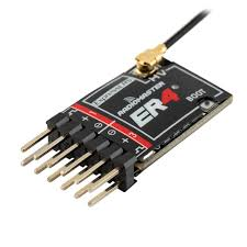
RX — Receiver
Compact ELRS receiver (Radiomaster ER4) installed in the RC car. Pairs with the TX over the ELRS protocol.
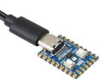
RP2040 — USB bridge
USB bridge between the PC and the TX. Runs our uart_bridge firmware so SimuRC-PRO can drive the TX via USB.
Alternative: Direct USB. Some TX modules (Ranger Micro, Ranger Nano, BetaFPV 1W Micro) can be connected directly to your PC by USB, removing the RP2040 from the chain entirely. If you choose this path, you can skip Step 2 (Flash RP2040) and Step 3 (Wiring RP2040 to TX) and follow the dedicated guide instead: Direct USB connection for ELRS TX modules.
Glossary: ELRS, FPV and key terms
Skim this glossary before starting if any of these terms are unfamiliar. The rest of the guide assumes them.
Radio link
- ELRS (ExpressLRS): open-source long-range radio control protocol used by drones, planes, and now this RC car simulator. The TX broadcasts, the RX receives.
- TX (Transmitter): the radio module that sends commands to the buggy.
- RX (Receiver): the radio chip inside the buggy that receives the commands.
- TX module: a standalone ELRS transmitter device (ATA Nano, Ranger Micro, etc.) you plug into the RP2040 or directly into the PC by USB.
- Binding passphrase: the shared secret between TX and RX. Both sides must have the exact same passphrase to pair.
- Wi-Fi config mode: a fallback mode where the TX or RX exposes a Wi-Fi hotspot at
http://10.0.0.1, used to configure the device. Triggered automatically when no radio link is established at startup. - Channel: a single signal line in the radio link. The ER4 has 4 channels (CH1 to CH4); CH1 and CH2 are used for throttle and steering. CH3 to CH8 are auxiliary (AUX) channels for extra functions.
- AUX (Auxiliary channels): CH3 to CH8. Map buttons or axes of your wheel to them to drive lights, accessories or future hardware on the buggy.
Hardware / electrical
- PWM: the analog-style signal used to drive RC servos and ESCs. The ER4 receiver outputs PWM. Drone receivers usually do not, and will not work here.
- UART: a simple serial link. The RP2040 board exposes a UART over USB so the PC can talk to the TX. It is the “COM” port you see in the software.
- RP2040: the dual-core microcontroller inside the Raspberry Pi Pico board, which we flash with our
uart_bridgefirmware to bridge PC USB to TX UART. - BEC: Battery Eliminator Circuit. The 5V output from the ESC that powers the RX via the 3-wire servo cable. No separate battery needed for the RX.
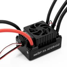
- ESC: Electronic Speed Controller. The motor controller inside the RC car. Receives PWM from the RX on CH2, drives the motor, and supplies the BEC.
- Baud rate: speed at which two devices talk over a serial link. The CRSF standard is 400000, but some USB bridges require a different baud (115200, 921600). SimuRC-PRO has a dropdown to pick the rate that works for your TX module in Direct USB mode.
App features
- Direct USB: connection mode where the TX module is plugged straight into the PC USB, skipping the RP2040. Available on selected ESP32-based modules.
- FFB (Force feedback): the motor inside a sim racing wheel that pushes back on the user. SimuRC-PRO uses it to simulate a centering spring.
- EXP (Expo curve): non-linear response curve around the center of an axis. Softens or sharpens the feel.
- TRIM: a small offset on the center of an axis. Used to correct a buggy that drifts slightly to one side.
- Dead zone: a small range around the rest position where the input is ignored. Filters out hardware noise or accidental nudges.
- ARM (Arming): safety state. The throttle stays at zero until the user explicitly arms the buggy via a long press on the ARM button.
- Failsafe: safety fallback. Throttle and brake are forced to zero, steering stays active. Triggered when the link is lost or the user presses ARM while armed.
- Throttle safety hold: automatic protection that refuses any throttle output until the pedal is observed at rest after a Connect.
Video (FPV)
- FPV (First Person View): a live video feed from a camera mounted on the buggy, displayed on a screen or in goggles.
- VTX: Video Transmitter. The board on the buggy that sends the camera feed over the air.
- OpenIPC / Wyvern / DJI O4: popular VTX modules. Wyvern is the one required to use the future SimuRC-PRO TrueFeel add-on. DJI O4 is the easiest plug-and-play setup with DJI goggles.
- UVC: USB Video Class. Standard that lets analog FPV USB capture devices show up as a webcam in VLC or OBS.
- RTL8812AU: the Wi-Fi chipset that works as a receiver for Wyvern/OpenIPC video on a PC. If you buy a USB Wi-Fi adapter for that, make sure it uses this exact chipset.
1. Install SimuRC-PRO and add your licence
Download, install and run SimuRC-PRO, then activate your licence.
Download page: hsimracing.com/product/simurc-pro/
2. Flash the RP2040 USB board
Skip this chapter if you use Direct USB. If your TX module is one of the ESP32-based modules that support Direct USB (Ranger Micro, Ranger Nano, BetaFPV 1W Micro), you do not need an RP2040 at all. Jump straight to the Direct USB guide, then come back here at Step 4 (Wiring the RC car).
2.1 Download the firmware
Firmware archive: hsimracing.com/uart_bridge-uf2/
Tip: click the link or copy/paste it. If you type it manually, note the underscore in uart_bridge.
Extract the archive and locate the file uart_bridge.uf2.
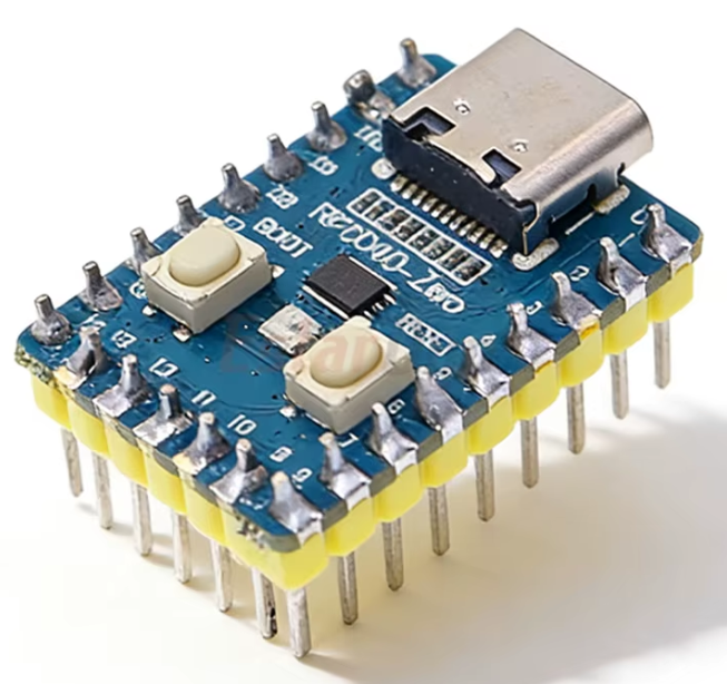
2.2 Put the RP2040 into bootloader mode
- Connect the RP2040 board to your computer via USB.
- The board has two small buttons labelled BOOT and RESET.
- Press and hold the BOOT button.
- While still holding BOOT, briefly tap RESET.
- Release the BOOT button. You should hear the Windows USB device connected sound. The board now appears as a USB drive in your file explorer.

2.3 Copy the firmware file
Copy uart_bridge.uf2 onto the newly mounted USB drive. The RP2040 will automatically reboot once the file transfer is complete (you will hear the Windows USB sound a second time).
2.4 Verify the installation
Open SimuRC-PRO. In the top-right corner you should see a COM port identifier such as COM(x). Firmware installed. The RP2040 board is ready to use.

3. Wiring the RP2040 to the TX
Skip this chapter if you use Direct USB (see the Direct USB guide).
The RP2040 USB board connects to your PC and to the back of the TX.
3.1 Powering the boards
Two power configurations are possible.
A. Recommended setup for first-time configuration and normal use: power the TX with an external 5V / 3A USB charger. In this configuration, connect all three wires between the TX and the RP2040 (Black, Red, White).
B. Alternative: power both devices directly from the PC using two separate USB ports (one for the RP2040, one with fast charging for the TX). Only the White wire is required between the TX and the RP2040. Black and Red are not needed in this case.
Important: when the TX is powered only from a PC USB port, some computers may not provide enough current for full TX power. This setup is therefore mainly suitable for firmware verification, configuration, or short-range testing, unless your PC has a high-power USB port capable of 5V / 3A.
3.2 Wiring diagram
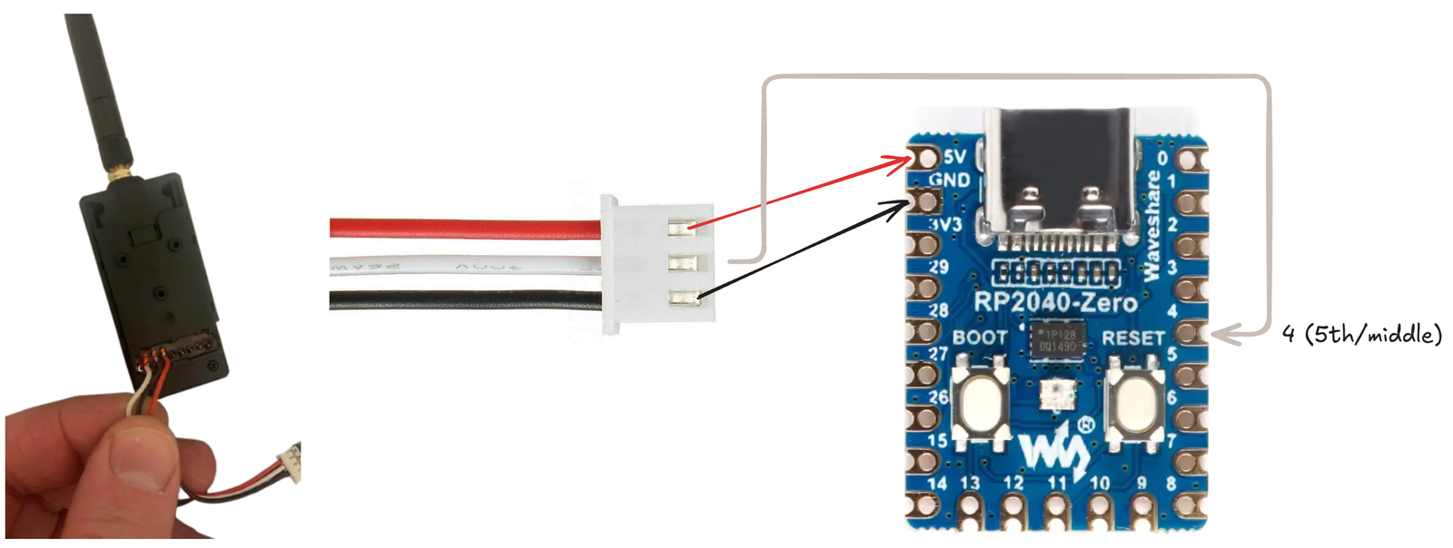
You can solder directly or use ready-made Male-to-Female Dupont wires:
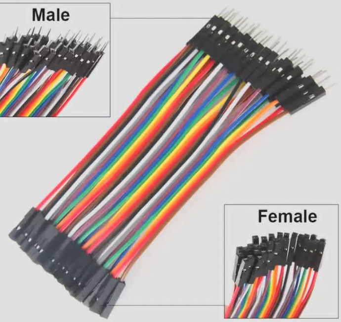
You need pin headers on your RP2040 to plug them in:
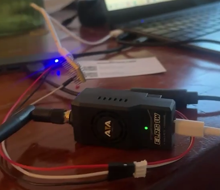
Final result:
4. Wiring the RC car
The RX (Radiomaster ER4) goes inside the RC car. Two of its four PWM channels drive the vehicle: one for throttle, one for steering.
4.1 Wiring diagram
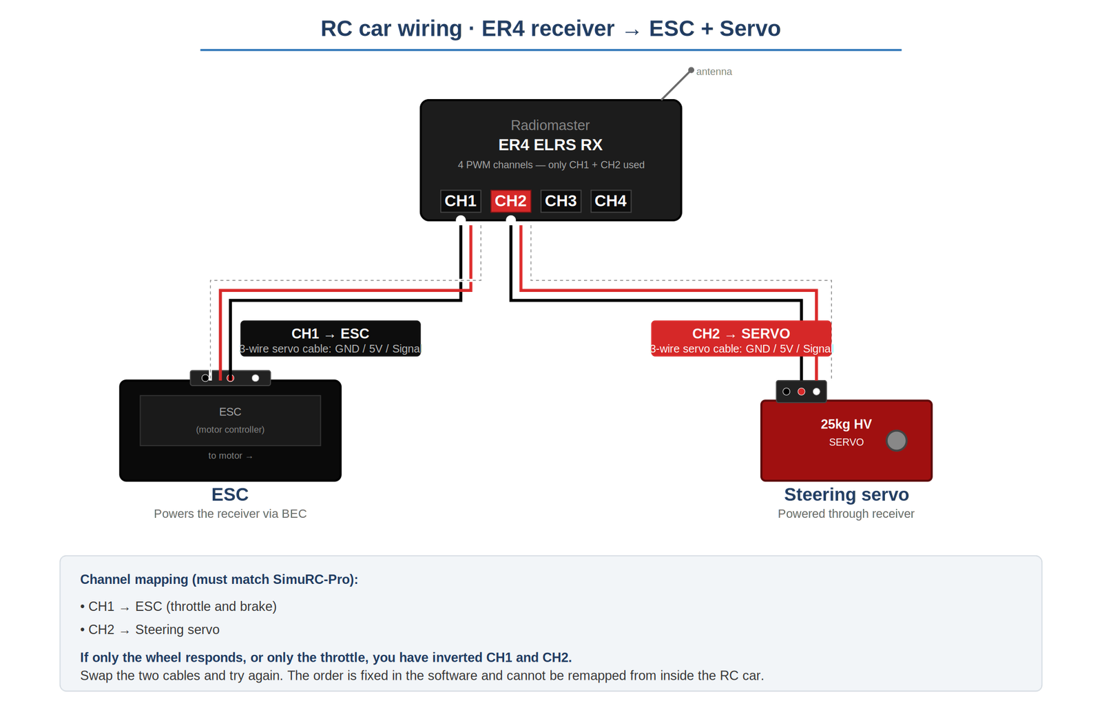
4.2 Channel assignment
SimuRC-PRO sends two PWM signals on fixed channels. The wiring inside the RC car must follow this order:
- CH1 → Steering servo
- CH2 → ESC (throttle and brake)
If only one of them responds. If only the wheel works (or only the throttle), the two cables are inverted on the RX. Swap CH1 and CH2 and try again. The order is fixed in SimuRC-PRO and cannot be remapped from inside the RC car.
4.3 Throttle and brake share a single axis
CH2 carries throttle and brake on the same axis: pushing forward = throttle, pulling backward = brake. SimuRC-PRO reads them as a single combined input from the controller.
4.4 AUX channels (optional)
CH3 to CH8 are auxiliary channels. SimuRC-PRO can map them to extra buttons or axes on your wheel/controller, so you can drive lights, accessories or future expansion hardware. The basic setup (CH1 + CH2) does not need them.
5. ELRS pairing (TX and RX)
Overview
In an ExpressLRS system, the TX and the RX must be paired using the same binding passphrase. The procedure is identical on both devices.
Critical prerequisite: the TX must be active (blue LED) before pairing can happen.
The RX waits for ELRS frames coming from the TX before it accepts a binding handshake. As long as the TX is not in radio mode (blue dimming LED), no frames are emitted, even if you have just powered everything on and entered the right passphrase. The RX will eventually fall back into Wi-Fi config mode and you will have to start over. Always click Connect in SimuRC-PRO first (which puts the TX in radio mode), and only then power the RX.
Important notes
- TX and RX form a single radio system. They must share the exact same binding passphrase.
- Due to their small size, RX modules have limited Wi-Fi antenna performance. Keep the RX very close to the phone or computer used for configuration.
- Wi-Fi Hotspot mode is always available. If no radio link is established shortly after power-up, the device automatically switches to it, even if already configured.
- You cannot test pairing until SimuRC-PRO is connected. The LIVE status (green DISCONNECT button) means data is flowing.
- Make sure you have completed the previous steps first, including connecting both USB cables (TX and RP2040).
Power requirements
RX power supply (RC car). The RX is powered by the RC car’s motor controller (ESC). Power is provided by the BEC output via a standard 3-wire servo cable.
Safety warning, RC car power. When powering the RC car to supply the RX, the motor may activate unexpectedly. Always remove the wheels from the RC car before applying power, or ensure the vehicle is securely lifted off the ground. This prevents accidental movement, injury or damage. We cannot be held responsible for any injury.
TX power supply. The TX must be powered via its USB port. This port is power input only. Data flows through the back connector, not through USB. Recommended: 5V / 3A USB charger (or a PC fast charging port). In long-range mode (up to 1W RF output), the TX requires significant power. An underpowered USB supply may cause unstable operation.
Pairing procedure
Step 1. Power either the TX or the RX. Since no radio link is established within a few seconds, the device automatically enters Wi-Fi Hotspot mode.
Step 2. On your phone or PC, connect to the ELRS Wi-Fi network. Password: expresslrs.
Reference screenshots (RX network on the left, TX network on the right):
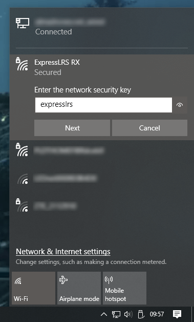
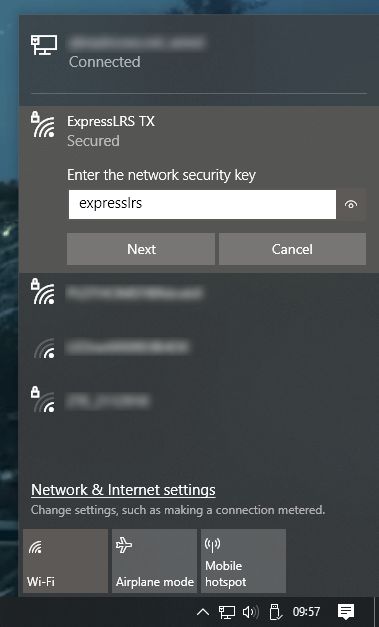
Step 3. If the page does not open automatically, open a browser and go to http://10.0.0.1/
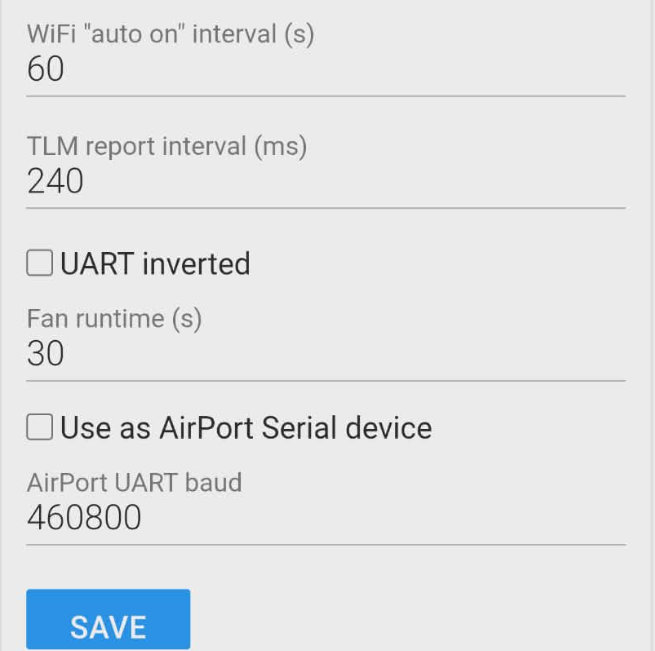
Step 4. Enter the exact same passphrase on both TX and RX. Check that UART inverted is NOT ticked. Click Save Configuration.
Step 5. Repeat for the second device. Once both devices share the same passphrase, the TX and RX will automatically bind each time they are powered on, as long as you connect SimuRC-PRO quickly enough (see the next chapter).
6. Axis Calibration (wheel and pedals)
This step is pure software: it reads your wheel and pedals through Windows and saves their calibration in SimuRC-PRO. You do not need the TX module or the RC car powered for this. Plug your wheel into the PC and you are good.
Click the Axis Calibration button in the app. The wizard walks you through steering (center, full left, full right), throttle and brake (min, max), shift paddles, and any auxiliary axis you want to use. Follow the on-screen instructions.

To verify Windows sees your hardware: press Windows Key + R, then type joy.cpl.
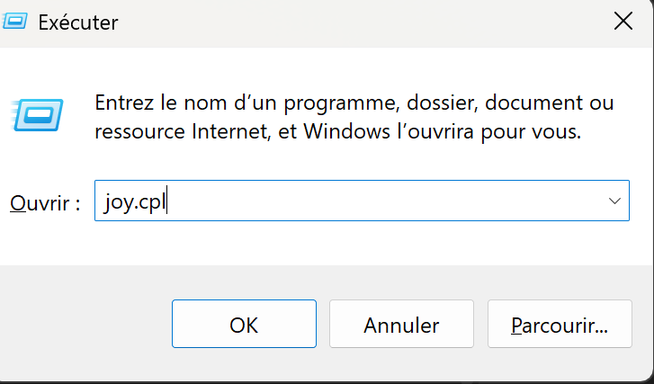
You should see your steering wheel and pedals listed.
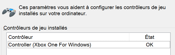
If they do not appear, you may need to plug them in, power them on, or install the manufacturer driver.
Logitech G29 note. The G29 pedals report 50% at idle until you touch each pedal once after plugging the USB. Press the throttle and the brake pedals briefly before calibration (and before clicking Connect later) so they jump to their real rest position. See Troubleshooting for details.
7. Power-up timing and Buggy Calibration
This chapter walks you through powering up everything in the right order and running the Buggy Calibration wizard. The wizard opens its own ELRS connection internally to move the servo and the ESC while you set the mechanical end-stops.
Why the main Connect button is greyed out at this stage. SimuRC-PRO locks the main Connect button until both Axis Calibration (Step 6) and Buggy Calibration (this chapter) are done. This is intentional: a buggy whose mechanical limits are unknown should not be driven. The Buggy Calibration wizard bypasses this lock by opening its own connection just for the duration of the wizard.
Timing matters. If the TX is not in radio mode when the RX powers up, the RX will switch to Wi-Fi mode and you will need to start over. The TX switches to radio mode when an ELRS connection is opened in SimuRC-PRO, which the Buggy Calibration wizard does for you.
Sequence
- Launch SimuRC-PRO on the PC.
- Plug the RP2040 USB board into the PC (or the TX directly if using Direct USB).
- Power the TX using its own USB port (5V / 3A charger or high-power PC USB port).
- Pick the matching COM port in the dropdown. The main Connect button stays greyed out, this is normal.
- Power the RC car. The RX should blink slowly waiting for the TX.
- Click Buggy Calibration. The wizard opens its own ELRS connection.
Visual check right after starting Buggy Calibration.
Within about one second of confirming the safety step in the wizard, you must see two changes:
- The RP2040 LED changes from solid red to blinking.
- The TX LED changes from orange-blinking to blue dimming.
If neither LED reacts, the three wires between the RP2040 and the TX are the culprit. This is by far the most common mistake. Check wire colors (Black / Red / White) and pin positions on both boards before touching anything else.
Buggy Calibration wizard
The wizard measures the real mechanical end-stops of your buggy (steering servo center / min / max, throttle neutral / min / max) in microseconds. Doing it once per buggy protects the mechanics: you will not over-drive the servo or push the ESC out of its valid range. Each saved buggy profile keeps its own mechanical limits, so you can switch between buggies without redoing the calibration.
Wheels off for Buggy Calibration. The servo and the ESC will move during this wizard. Keep the wheels off the ground or removed so any unexpected motion stays harmless.
When you close the wizard, the internal ELRS connection closes too. The main Connect button is now unlocked. Move on to the next chapter to start driving normally.
If the device list is empty in SimuRC-PRO
The RP2040 USB board is not connected to the PC or not yet configured. Go back to Step 2 and push the firmware file onto it.
The blue light is the key
On the TX, watch the LED carefully:
- ● Blue dimming on TX: OK, ready to power the RC car.
- ● Green light: Wi-Fi mode (configuration). You are too late. Unplug everything and restart from step 2.
If the RC car is not powered within about 60 seconds of seeing the blue dimming, the RX falls back into Wi-Fi mode. Unplug everything and restart from step 1.
LED status reference
| Device | Colour / behaviour | Status |
|---|---|---|
| RP2040 USB board | ● Red | Not connected |
| RP2040 USB board | ● Blinking | Connected |
| TX (Radiolink ATA Nano 1W) | ● Blinking orange | Not connected |
| TX (Radiolink ATA Nano 1W) | ● Blue | Connected |
| TX (Radiolink ATA Nano 1W) | ● Green / blue dimming | Pairing mode (Wi-Fi) |
| RX (Radiomaster ER4) | ● Solid on | Connected to TX |
| RX (Radiomaster ER4) | ● Slow blink (500 ms) | Waiting for connection from TX |
| RX (Radiomaster ER4) | ● Double blink then pause | Binding mode |
| RX (Radiomaster ER4) | ● Fast blink (25 ms) | Wi-Fi mode (configuration) |
Safety features (read once, never forget)
SimuRC-PRO assumes you are driving a real RC car with real consequences. Three safety layers run constantly to prevent the buggy from bolting unexpectedly.
Explicit arming (ARM button)
Throttle stays at zero until you arm the buggy. To arm, do a long press (3 seconds) on the ARM button you mapped on your wheel or button box. Any short press on the ARM button when armed triggers a failsafe (throttle and brake forced to zero, steering stays usable). Steady ground only, then re-arm with another 3-second press. You can disable explicit arming in the settings if you really want, but we strongly advise keeping it on for any buggy more powerful than a toy.
Throttle safety hold
Every time you click Connect, SimuRC-PRO refuses to forward any throttle until it sees your throttle pedal physically at rest (under 5%). Once it sees the pedal released, the hold lifts for the rest of the session. This protects you from a stuck or uncalibrated pedal that would otherwise launch the buggy at full throttle the second the link goes live.
Connection state machine
The status indicator at the bottom of the main window reports one of three states:
- LIVE: link healthy, inputs flowing to the buggy.
- FAILSAFE: input lost or arming dropped. Throttle and brake forced to zero, steering still active.
- RECOVERING: link came back, waiting for inputs to confirm a safe state before resuming live mode.
If your wheel USB cable accidentally disconnects, the system enters FAILSAFE automatically. When you plug it back, it transitions through RECOVERING and resumes LIVE once everything looks right.
8. Start using SimuRC-PRO
SimuRC-PRO is multilingual and includes a built-in HELP button if you need a refresher inside the app.
Recommended first run
- Calibrate the buggy.
- Test slowly using the low-power profile. On profile 1, you cannot send more than 20% throttle.
- Add a video feedback to your PC, or use an FPV helmet.
Reading the interface
Physical inputs as received and calibrated:

Actual signal sent to the buggy receiver:

Live tweaking sliders (similar to a generic RC radio):

Open the Buggy Monitor window (button in the top bar) for a larger overlay you can keep on a second screen, showing the same live data in a layout suited for streaming or a dedicated cockpit display.
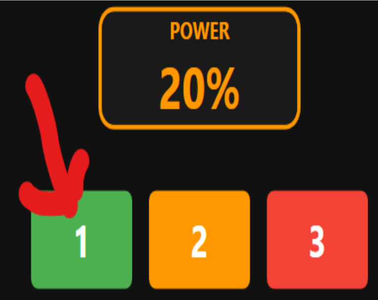
Power profiles
Three power levels cap the maximum throttle sent to the buggy:
- Beginner 20%: learn without breaking anything. Recommended for the first runs.
- Intermediate 50%.
- Expert 100%: full power, full risk.
Switch between them with the buttons in the top bar. The cap applies on top of all the other safety layers.
EXP, TRIM and dead zone
Each axis (steering, throttle, brake, AUX) has its own EXP, TRIM and dead zone settings.
- EXP makes the axis more or less sensitive around its center (steering) or its released position (throttle, brake). Positive EXP softens the response near the center. Negative EXP sharpens it.
- TRIM shifts the center / released position slightly. If your buggy drifts a little to the right, trim to the left to correct it.
- Dead zone ignores small movements around the center / released position. Useful if your hardware has a bit of noise or if you accidentally bump the wheel.
Force feedback (steering spring)
SimuRC-PRO simulates a centering spring through your wheel’s force feedback. Two sliders control it:
- FFB SPR: spring strength. How hard the wheel pulls back toward the center.
- FFB SPD: speed factor. The spring gets stronger as the buggy goes faster (closer to the feel of a real car).
The Test FFB button (next to the sliders) runs a short 5-second sequence to validate strength and direction:
- Active recenter (1 s)
- Pull left (1 s)
- Silence (1 s)
- Pull right (1 s)
- Active recenter (1 s)
A confirmation popup describes the sequence before it runs (the wheel is about to move on its own, hold loosely or let it free). If left and right are inverted on your wheel, tick the Invert FFB checkbox and run the test again. The invert applies to MOZA SDK and DirectInput wheels (Fanatec, Logitech, Thrustmaster, etc.) uniformly.
Virtual gearbox
Enable the Virtual gearbox checkbox and SimuRC-PRO simulates a 6-speed gearbox on top of your throttle pedal. Shift up and down with the paddles mapped during calibration. The simulated RPM is shown in the interface and influences the power delivered to the buggy: a real “gearbox feel” on an RC, just for fun. The simulated power factor slider (0.5x to 6x) lets you scale how aggressive the gearbox is.
AUX channels
Map extra buttons or axes on your wheel to CH3 through CH8. Use them to drive lights, accessories or any future expansion hardware on the buggy. Not required for basic driving.
Background mode
When the SimuRC-PRO window loses focus (typically when your FPV video player takes the foreground), the control loops keep running so you can keep driving. The status indicator switches to a discreet “background” hint but the buggy keeps receiving your inputs. This is the standard way to use the app in real FPV sessions.
Drift setup tip
If you want to drift, set EXP to -0.5 for steering. You can also go to Axis Calibration and, when prompted for max left / right, only turn the wheel partially instead of using its full physical range.
Updates are automatic
SimuRC-PRO updates itself. On each launch it quietly checks for a new version, downloads it in the background, and installs it the next time you start the app. Nothing to download by hand, and a running session is never interrupted.
Your settings and licence are stored in %APPDATA%\SIMU-RC-Pro and are kept across every update, so you never lose your calibration or have to re-enter your key.
Want early builds? In Settings → Updates, tick Receive development (beta) updates to switch to the development channel (it may be less stable). Leave it unchecked to stay on the stable channel (recommended).
Coming from an older version? Download and run the installer once from your account / the product page; from then on updates are automatic.
Join the community
Share your buggy, your setup, ask for help, get notified of new releases. The Discord is the fastest channel to reach us.
If something does not work as expected: Troubleshooting →
Need a Direct USB setup (no RP2040): Direct USB connection for ELRS TX modules →
Thanks for your trust.
Julien Raidelet, CEO, hsimracing.com